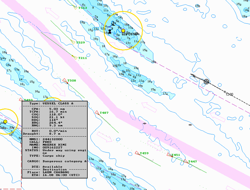
 AIS stands for Automatic Identification System, an active primary safety system for vessels at sea. The black arrow in the photo at right, captured from our PC screen, is Crystal Blues. The red arrows (targets) are ships we want to avoid. Clicking on a target reveals the data box seen at bottom left - lots of information on the ship in question (click the image at right to enlarge).
I met a cruising sailor last night who said that my first AIS story (here) was very technical - oops, I guess it is a technical subject. Not sure that I can eliminate the technicalities, but I will try to explain them. First though, an essential technology primer .... I strongly recommend you spend time roaming the excellent PANBO website, specially the AIS pages. Also, here are links for two very informative and useful documents, covering co-axial connectors and co-axial cabling. OK, on with the story ....
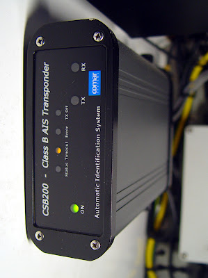
We purchased our Class B AIS transponder from Oceantalk in Singapore - in fact we bought four of them, as several other boats wanted to install the system. The unit is a Comar CSB.200, manufactured in the United Kingdom. It was supplied by Oceantalk with a Shakespeare VHF whip antenna and a Sanav GPS antenna.
All Class B AIS transponders require a dedicated GPS receiver and a dedicated VHF antenna. No arguments please - if you want this powerful safety system, you have to install the extra antennae. No, you cannot share signals from existing systems, however the AIS derived GPS position information is available to you as a separate NMEA signal, for chart plotting purposes. You'd better plan carefully for antenna locations, bracket positions and cable runs.
The GPS antenna is a simple patch antenna with a low noise amplifier that sends the received signals (as RF) direct to the AIS system for timing analysis - in other words, the external receiver is just an amplified antenna, and all the complex decoding and mathematical computations to derive your vessel position occur inside the AIS transponder. This is a specific requirement of the IMO AIS regulatory framework - it basically ensures that no one can feed fake vessel positions into the system. That is good to know ...
On the VHF side, AIS Class B uses just 2 watts of radiated power to send its reports outwards (the big ships get 12 watts). It is easy to receive signals from big-ship class A systems, however you better pay attention when installing your VHF cables, connectors and antenna. You want to ensure that all of your 2 watts is actually radiated into the ether. Robin Kidd from Oceantalk stressed this point - make sure your VHF cabling and connection work is good. Installation requires the following :
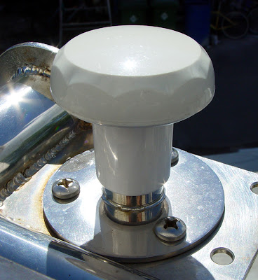
- Physically mount the AIS box. A U-bracket is supplied, but we used industrial strength adhesive Velcro to mount it on a vertical bulkhead (see photo).
- Run the cables for VHF and GPS antennae
- Install and connect both antennae
- Run cable for DC power with a fuse in line
- Run the data cable to the chart plotter/display system
- Terminate everything and then commission the system
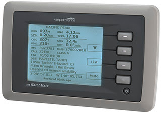
Of course your chart plotter must be compatible with AIS messages in NMEA format to display the targets and information. If it isn't, you can use this very neat AIS display from Vesper Marine, the AIS Watchmate, or a more serious display (with charts) made by Comar, the CSD.200.
Back to the installation. If you power the box from a shared DC circuit breaker (ours is on our navigation instruments circuit) you should include a 5amp fuse in the power feed. Be careful with the VHF antenna cabling - OK, its just RG.58, but you've only got 2 watts to radiate, so make sure you use high quality connectors and fittings.
The GPS receiver supplied by Oceantalk is the RV-76, made by San Hose Technology in Taiwan. It includes a nice 10 metre pre-terminated cable. Its very thin, and easy to run through the boat, but it turns out to be RG.174, which has very high losses (attenuation) at these frequencies
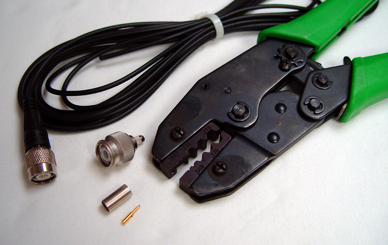 (1.5ghz). If you use the supplied cable as-is, with its existing terminations, it will work just fine. However if you need to cut, join, extend or splice (as we did), then you'll have to use a more suitable cable (RG.223). After attempting to extend the supplied cable, and getting no satellite signal, we changed to a Bedea RG.223 with Telegartner crimp connectors - voila, tons of signal. We purchased the cable and connectors from Coastal Electronics in Singapore, though similar cable is made by Belden and others. Make sure you use the correct crimping tool (see photo).
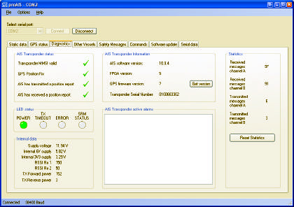
On the VHF side, the Comar AIS box will actually measure and report the SWR (reflected energy ratio) on your VHF transmission line during commissioning - you'll soon know if your VHF cabling and connectors are good or not. Click on the photo below at right to see typical values.
 With all that hard work done the rest was easy - plug the box into our PC using the supplied cable and configure the COM port on the PC (baud rate etc) . Then load the Comar software (supplied) and configure the unit. At this point you'll be asked to input your vessel identifier, which is the unique "MMSI number" issued by your National Marine Authority. If you don't have an MMSI number you'd better apply for one now, because you cannot transmit using AIS without one. A Comar Class B transponder will stay in "receive only" mode until you give it your MMSI number. The real trick is that this number can only be entered ONCE by the user - mess it up and you have to send the box back to the dealer for resetting.
I've just learned that Class B systems are FINALLY approved for use in the USA (story here), but that they are not allowing users to configure the MMSI identifiers. I bet that will be fun to administer.... seems the installers or retailers will have to configure the box before handover. The Comar configuration software is simple to use, neat and logical.
So, use only good cables and connectors, get yourself an MMSI number and enjoy the results. Our next story on AIS will conclude the series with our user experiences.
No comments:
Post a Comment
Have something to say ? Let us know your thoughts ....